
Plastic Injection Mold Tooling: Design, Manufacturing, and Applications
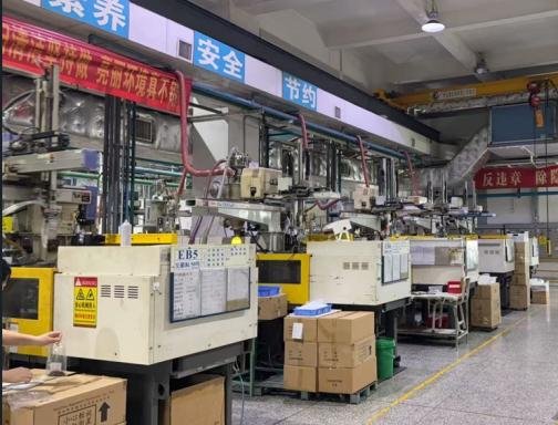
Plastic injection mold tooling can look straightforward when a 3D model appears complete, but many projects fail because key production risks are still hidden. A low initial tool price, vague tolerance notes, or an incomplete DFM review can create costly modifications, missed launch targets, and unstable parts later. I approach tooling as a production strategy, not simply a machining task.
Plastic injection mold tooling is the engineered system of mold design, steel selection, cooling, gating, ejection, and validation used to produce repeatable plastic parts at the required quality and volume.1 The right tooling strategy starts with the final application, material behavior, critical tolerances, appearance expectations, inspection method, and production forecast—not only with the customer’s CAD drawing.
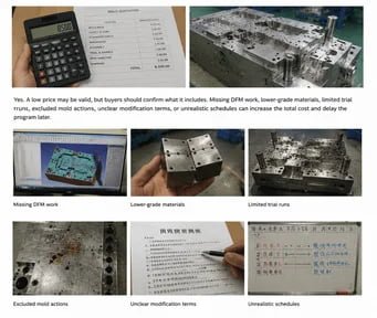
A mold can produce one acceptable sample and still create risk during regular production. In my experience, the important question is not only whether the tool can make a part at T0. The better question is whether it can make stable, measurable, repeatable parts over batches, shifts, and planned production volumes.
Why Should Plastic Injection Mold Tooling Start With the Product Application?
Plastic injection mold tooling decisions become unreliable when they begin with mold terminology instead of product function. A product team may ask for a two-cavity or four-cavity tool, but the more important questions involve use conditions, material selection, dimensional stability, cosmetic standards, and annual demand. If these inputs are unclear, the tool design may solve the wrong problem.
The best plastic injection mold tooling starts by reverse-engineering the finished part’s application and production requirements. We first assess how the component will be used, what material it needs, which dimensions are critical, how it will be inspected, and how many parts are required. These details guide cavity count, gate design, steel choice, cooling, ejection, and validation planning.
A drawing is necessary, but it is not enough
A 3D drawing is the starting point for a tooling quotation. It is not the full engineering brief. A drawing may show dimensions, draft angles, and basic material notes. However, it often does not show which dimensions are functionally critical, which surfaces customers will inspect visually, or how the part will behave after assembly.
In mold project communication, I often see parts that appear simple on screen but have demanding performance requirements. For example, a small medical-related plastic component may require:
- Stable dimensions after molding and storage
- A controlled surface finish for visual inspection
- Reliable fit with another component
- Minimal distortion around thin walls or locating features
- Consistent production across multiple lots
- Documented measurement points for acceptance
These needs affect tooling from the beginning. A gate placed in the wrong location can create visible flow marks, stress concentration, or warpage.2 Inadequate cooling may increase cycle time and dimensional variation.3 An aggressive ejection design can mark a polished surface or deform a thin part.
Material behavior changes the tooling approach
Different resins shrink, flow, cool, and respond to processing conditions differently.4 Even within the same polymer family, reinforced grades, flame-retardant grades, transparent grades, and medical-use grades can behave differently enough to affect the mold design.
| Product requirement | Tooling question we need to answer | Potential risk if ignored |
|---|---|---|
| Tight assembly fit | Which dimensions are truly functional? | Repeated fitting issues after molding |
| High cosmetic quality | Where can the gate and ejector marks be placed? | Visible defects on customer-facing surfaces |
| Glass-filled material | Does the steel and gate design suit abrasive flow? | Faster wear and unstable surface quality |
| Transparent optical-related part | How will polish, venting, and flow marks be controlled? | Reduced clarity or visible defects |
| High-volume production | What cycle time and cavity count are realistic? | Capacity shortfalls and high unit costs |
For precision medical molding projects, I find that the risk is usually not only machining accuracy. The larger question is whether the design supports stable production. A mold can be machined accurately to the CAD data, yet still struggle because the part design, material behavior, gate position, or cooling balance was not sufficiently considered.
I treat customer input as a risk-control step. More clarity before steel cutting usually means fewer surprises after the first trial.
What Information Should We Confirm Before Designing Plastic Injection Mold Tooling?
Plastic injection mold tooling becomes expensive when important requirements remain assumptions. Teams sometimes send a model and request a quick quotation, yet they may not have finalized the material grade, annual volume, inspection approach, or appearance standard. These missing details can later cause design changes that were avoidable.
Before designing plastic injection mold tooling, we should confirm the part application, resin grade, projected volume, critical tolerances, cosmetic requirements, inspection methods, assembly interfaces, and acceptance criteria. This information allows the supplier and project team to identify risks before steel is cut, rather than discovering them through repeated mold modifications.
The essential pre-tooling checklist
I recommend that project managers prepare a structured input package before requesting final tooling approval. The package does not need to be perfect. However, it should make known requirements visible and label open items honestly.
A practical tooling input checklist includes:
-
3D CAD files and 2D drawings
We need the latest revision-controlled files. Important dimensions should be clearly identified. -
Material specification
We should know the exact resin family, grade where available, color, filler content, and any special performance requirements. -
Annual volume and expected product life
A prototype tool, a bridge-production tool, and a high-volume production mold require different investment decisions. -
Tolerance priorities
Not every dimension needs the same control level. I encourage teams to identify critical-to-function dimensions rather than applying unnecessarily tight tolerances everywhere. -
Appearance requirements
We should clarify surface texture, gloss, weld line acceptance, gate vestige limits, sink-mark expectations, and visible-side definitions. -
Assembly and mating-part information
A molded part may pass its own dimensional inspection but fail in assembly. Mating geometry and functional fit information are valuable. -
Inspection and acceptance plan
We should agree on how the part will be measured. This may include CMM measurement, pin gauges, visual standards, weight checks, functional fixtures, or customer-provided gauges.
Why tolerance notes need context
A tight tolerance is not just a number on a drawing. It affects mold construction, processing windows, measurement repeatability, and the time needed for trial optimization.5 A dimension may be difficult to control because of material shrinkage, thin-wall geometry, long flow length, or proximity to a gate.
In one anonymized project, a customer initially specified several tight dimensions without identifying which ones controlled the final assembly. During DFM communication, we learned that only two locating features had a direct functional role. This allowed the team to focus the tooling strategy and measurement work where it mattered most. The remaining dimensions still required control, but they did not need the same level of optimization.
That distinction can protect both cost and schedule. It also makes acceptance discussions more objective after T0 and T1.
How Do We Evaluate Plastic Injection Mold Tooling Beyond the Initial Price?
Plastic injection mold tooling with the lowest quotation can become the highest-cost option if the scope does not address production risk. A low number may exclude meaningful DFM work, trial planning, spare components, measurement support, or necessary design details. The cost then returns later through rework, delays, rejected parts, or unstable output.
We should evaluate plastic injection mold tooling by total project risk, not by mold price alone. A useful evaluation compares the supplier’s DFM depth, technical communication, steel and component plan, trial process, measurement approach, modification assumptions, and ability to support stable production after initial samples are approved.
The hidden cost of an incomplete tooling scope
A tooling quotation can look comparable while covering very different levels of engineering work. For this reason, I advise customers to review what sits behind the price.
| Evaluation area | Questions to ask | Why it matters |
|---|---|---|
| DFM review | Does the supplier identify draft, wall thickness, undercut, and shrinkage risks? | Early changes are cheaper than post-T0 modifications6 |
| Mold concept | Are cavity count, gate type, and runner system explained? | These choices affect quality, cycle time, and waste |
| Steel selection | Is steel matched to resin, surface finish, and expected life? | The wrong choice may affect wear, polish, and maintenance |
| Trial plan | How many trials are included, and what will be checked? | T0 alone may not prove production stability |
| Measurement | Who measures critical dimensions and by which method? | Results need to be comparable and actionable |
| Modification process | How are changes assessed, approved, and documented? | Unclear changes create delays and scope disputes |
| Delivery scope | Does the price include samples, reports, spare parts, and export packing? | Missing items can distort the true project cost |
A cheaper tool can create a longer route to production
I have seen projects where the initial quote looked attractive because the proposed approach was very basic. The supplier may have accepted the CAD model without raising questions about gating, part deformation, ejection marks, or inspection points. The customer then received samples, but the samples became the beginning of a long correction cycle.
This does not mean every lower-priced mold is poor, and it does not mean every higher-priced mold is automatically better. It means the project team should understand the reasoning behind the proposal.
A transparent supplier should be able to explain:
- Why a particular cavity layout was selected
- Why a cold runner or hot runner was recommended
- Where the gate will be located and what trade-offs it creates
- How cooling will support cycle time and part stability
- Which dimensions may need adjustment after real molding trials
- What trial results will be reviewed before the next action
Tooling cost and part cost must be considered together
A high-cavity mold may reduce unit cost at volume, but it also increases tooling investment and complexity. A hot runner may reduce runner waste, but it adds maintenance and process considerations.7 Hardened steel may suit long production life, but it is not always necessary for low-volume programs.
The right choice depends on the product’s commercial reality. I encourage customers to compare at least three cost layers:
- Initial tooling investment
- Expected part cost during planned production
- Risk cost from delays, modification loops, scrap, and downtime
This is why I describe tooling as a manufacturing strategy. The mold price is important, but it is only one part of the decision.
When Is Plastic Injection Mold Tooling Ready for Stable Production?
Plastic injection mold tooling is not proven simply because T0 produces a part that looks acceptable. First samples can reveal whether the concept works, but they may not show variation across cavities, cycles, material lots, or normal operating conditions.8 Production readiness requires evidence that the process can be repeated with control.9
Plastic injection mold tooling is ready for stable production when trial results show that the mold can repeatedly produce parts that meet agreed functional, dimensional, and appearance requirements under a defined processing window. T0 validates the initial concept, while T1 and later trials should confirm corrections, measurements, process consistency, and practical production behavior.
What T0 should tell the project team
T0 is commonly the first molding trial after the mold is assembled. It is an important milestone, but I do not view it as a final judgment of mold quality. T0 should provide information about how the design behaves in real resin flow and cooling conditions.
During a T0 review, we may assess:
- Whether the mold opens, closes, ejects, and cycles correctly
- Whether filling is balanced across cavities
- Whether the gate location produces acceptable flow behavior
- Whether short shots, flash, sink marks, burns, or weld lines appear
- Whether cooling appears balanced
- Whether the part releases without deformation or surface damage
- Whether initial dimensions are near the intended target
The purpose of T0 is to identify the gap between the design assumptions and the molded reality. That gap is normal. The key is how clearly the supplier documents findings and how logically the team decides the next actions.
T1 should move from “sample exists” to “part performs”
T1 often follows modifications based on the first trial. At this stage, the team should not only inspect a few visually good samples. We should compare measurements against agreed criteria and assess whether improvements are stable.
For higher-risk components, I recommend documenting:
- Trial date and machine conditions
- Material identification and drying conditions where relevant
- Cavity identification for multi-cavity molds
- Sample quantity and sampling plan
- Critical dimension results
- Visual inspection findings
- Weight or other practical consistency checks
- Open issues and agreed corrective actions
In precision molding work, a tool that produces one acceptable sample is not necessarily ready for repeated production. A part can change due to normal variation in material condition, processing setup, mold temperature, or cavity balance. Therefore, the project team should define what “accepted” means before trial samples arrive.
Stable production is a shared responsibility
The mold supplier controls an important part of the system, but stable production also depends on the molder, material control, machine capability, process setup, inspection discipline, and part handling. I believe this shared view creates better communication.
When a project team asks, “Can this mold make the part?” I prefer to expand the question:
Can this complete molding system make the part consistently, inspect it reliably, and support the intended production volume?
That is the more useful standard for production-oriented tooling decisions.
How Does Plastic Injection Mold Tooling Support Different Applications?
Plastic injection mold tooling must match the application because different products fail in different ways. An automotive interior component, a precision medical-related part, and an optical lens-related component may all use injection molding, yet they can require very different priorities for surface finish, dimensional control, traceability, material handling, and mold maintenance.
Plastic injection mold tooling supports diverse applications by adapting the mold concept to the part’s functional risks. Automotive parts may prioritize durability and fit, medical-related components may require strong dimensional and visual consistency, while optical and camera-related products may require careful attention to polish, flow behavior, and surface protection.
Automotive plastic components
Automotive projects often involve demanding fit, appearance, durability, and production-volume expectations. A small locating feature can affect assembly. A visible surface can create rejection risk. A glass-filled resin can increase wear in gates and cavities.10
For these projects, tooling discussions often include:
- Multi-cavity layout and cavity balance
- Wear resistance for filled materials
- Surface texture consistency
- Parting-line placement
- Gate vestige control
- Long-term maintenance planning
Precision medical-related components
For medical-related plastic products, I avoid treating all projects as identical because customer requirements vary widely. However, we often see strong focus on dimensional repeatability, clean visual surfaces, material control, functional fit, and documented inspection requirements.
The mold design should support those priorities. For example, a critical sealing area may require careful gate and ejection planning. A thin section may require balanced flow and cooling. A functional assembly may require measurement methods that reflect real use rather than only nominal drawing dimensions.
Optical and camera-related plastic parts
Optical lens and camera-related applications can be especially sensitive to surface quality. Tool polish, cavity protection, venting, gate strategy, handling, and process control all influence the final part appearance.11
I have learned that surface requirements must be discussed early. A request for a highly polished cavity surface is not enough by itself. The team should also clarify:
- Which surfaces are optically or visually critical
- Whether flow marks are acceptable in non-critical areas
- How parts will be handled after molding
- Whether gate marks can be hidden or must be minimized
- How the customer will inspect the surface
These conversations turn a general mold request into a more realistic production plan.
Frequently Asked Questions
What is included in plastic injection mold tooling?
Plastic injection mold tooling usually includes the mold base, core and cavity inserts, runner or hot-runner system, cooling channels, ejection system, slides or lifters where needed, and supporting mold components. The exact scope should also clarify trials, samples, inspection reports, spare parts, and export packaging.
How long does plastic injection mold tooling take to manufacture?
Manufacturing time depends on mold size, complexity, cavity count, steel selection, surface finish, purchased components, and modification needs after trials. A supplier should provide a project-specific schedule, but I recommend treating T0, T1, measurement review, and final adjustments as part of the overall timeline.
What is the difference between T0 and T1 in injection mold trials?
T0 is generally the first molding trial after the tool is assembled. It checks whether the initial mold concept works in real production conditions. T1 follows modifications from T0 and should confirm whether key dimensional, appearance, filling, cooling, and ejection issues have improved.
How should we choose the right cavity count for a mold?
The right cavity count depends on annual volume, cycle time, machine capacity, budget, part size, quality risk, and expected product life. More cavities can reduce unit cost at higher volumes, but they increase tooling investment and make cavity balancing and maintenance more complex.12
Why do molded dimensions change after the first trial?
Molded dimensions can change because plastic shrinks and responds to material condition, wall thickness, gate location, cooling, packing, and processing settings. A well-managed tooling project uses trial measurements to understand these effects and adjust the tool or process based on agreed critical dimensions.
Conclusion
Plastic injection mold tooling should be evaluated as a complete production-risk decision, not as a simple request to machine a mold from a drawing. I recommend starting with the product application, material, volume, tolerance priorities, appearance expectations, and inspection plan. Then, review DFM findings, tooling scope, T0 and T1 results, and evidence of stable production. If you are sourcing precision molds or molded components for a European or US project, contact our team to discuss your drawings, production goals, and potential tooling risks before steel is cut.
"Advanced Injection Molding Methods: Review - PMC", https://pmc.ncbi.nlm.nih.gov/articles/PMC10489002/. A technical educational source on injection mold design describes tooling as an integrated system that includes the mold cavity and core, runner or gate design, cooling channels, ejection mechanisms, and material-dependent production considerations. Evidence role: definition; source type: education. Supports: The source should define injection mold tooling or injection mold design as including mold structure, runner/gate systems, cooling, ejection, materials, and production considerations.. ↩
"Accounting for Residual Stress in Injection Molded Parts", https://madisongroup.com/accounting-for-residual-stress-in-injection-molded-parts/. Research on injection molding gate design reports that gate position affects melt-flow paths, pressure distribution, residual stress development, and deformation outcomes such as warpage, giving technical support to the link between gate placement and part defects. Evidence role: mechanism; source type: paper. Supports: The source should show that gate design or gate location influences melt flow patterns, residual stresses, weld/flow marks, and warpage in injection molded parts.. Scope note: The evidence would be contextual because the severity and type of defect depend on part geometry, polymer, tooling temperature, and processing conditions. ↩
"(PDF) A computational model for the cooling phase of injection moulding", https://www.academia.edu/16784309/A_computational_model_for_the_cooling_phase_of_injection_moulding. Studies of injection mold cooling systems show that cooling-channel layout and mold-temperature control are major determinants of cooling time, shrinkage distribution, warpage, and dimensional accuracy in molded parts. Evidence role: mechanism; source type: paper. Supports: The source should support that cooling-channel design and mold temperature control influence cycle time, shrinkage, warpage, and dimensional consistency.. Scope note: This supports the general engineering relationship, not a quantified cycle-time or variation estimate for the article's example parts. ↩
"The Effects of Cooling and Shrinkage on the Life of Polymer 3D Printed ...", https://pmc.ncbi.nlm.nih.gov/articles/PMC8839029/. Polymer-processing references explain that resin type and grade influence melt flow, shrinkage, cooling behavior, and sensitivity to molding parameters, which provides the material basis for adapting mold design to the selected plastic. Evidence role: mechanism; source type: education. Supports: The source should explain that polymers and resin grades have different melt-flow, shrinkage, crystallization/cooling, and processing-window characteristics in injection molding.. Scope note: This would support the general mechanism, not prove the behavior of any particular resin grade used in a specific project. ↩
"The Ultimate Guide to Injection Molding Tolerances", https://www.fictiv.com/articles/injection-molding-tolerances-an-in-depth-look. Technical guidance on plastic-part tolerancing notes that molded-part dimensions are affected by material shrinkage, mold construction accuracy, process capability, geometry, and measurement method, supporting the view that tight tolerances require coordinated tooling, processing, and inspection control. Evidence role: general_support; source type: institution. Supports: The source should explain that achievable tolerances in plastic injection molding depend on material shrinkage, mold accuracy, process capability, measurement method, and part geometry.. Scope note: The support is general; the achievable tolerance for any individual feature must be evaluated using the specific resin, geometry, tooling design, and measurement system. ↩
"DETC2003/DFM-48133 - Institute for Systems Research", https://isr.umd.edu/Labs/CIM/projects/dfp/dfm2003.pdf. Design-for-manufacturing literature commonly finds that early design decisions commit a large share of downstream manufacturing cost and that later engineering changes are typically more expensive and disruptive than changes made before tooling is built. Evidence role: general_support; source type: research. Supports: The source should support the general principle that costs and change difficulty increase as a product moves from design into tooling, testing, and production.. Scope note: This provides general product-development support rather than a measured cost comparison for T0 modifications in a specific mold project. ↩
"The Development Of A Hot Runner System For High Precision Injection ...", https://preserve.lehigh.edu/_flysystem/fedora/2023-11/preservebp-13881544.pdf. Educational materials on injection molding runner systems describe hot runners as reducing or eliminating cold-runner scrap while requiring additional thermal control, maintenance, and tooling complexity compared with simpler cold-runner designs. Evidence role: general_support; source type: education. Supports: The source should describe the common trade-off that hot runners eliminate or reduce runner scrap while adding temperature-control, maintenance, and tooling-complexity considerations.. Scope note: The economic balance depends on resin cost, production volume, part geometry, cycle time, and maintenance capability. ↩
"Process Validation: General Principles and Practices", https://www.fda.gov/files/drugs/published/Process-Validation--General-Principles-and-Practices.pdf. Process-validation guidance emphasizes that production processes should be shown to operate reproducibly under defined conditions, including normal variation in inputs and operation, which supports distinguishing acceptable first samples from evidence of stable production. Evidence role: expert_consensus; source type: government. Supports: The source should support that process validation requires evidence of reproducible output under defined operating conditions, not only acceptable first articles.. Scope note: The guidance is usually framed for regulated manufacturing and process validation; it supports the principle rather than defining T0 sampling requirements for all injection molding projects. ↩
"Process Validation: General Principles and Practices", https://www.fda.gov/files/drugs/published/Process-Validation--General-Principles-and-Practices.pdf. Government process-validation guidance defines validation as establishing objective evidence that a process can consistently produce output meeting predetermined specifications, supporting the article's statement that production readiness requires repeatable control. Evidence role: expert_consensus; source type: government. Supports: The source should state that validated or production-ready processes must consistently produce output meeting predetermined specifications under controlled conditions.. Scope note: This is a general validation principle and does not specify the exact number of molding trials or samples required for a particular non-regulated product. ↩
"Design and Optimization of the Injection Molding Process of Glass ...", https://openprairie.sdstate.edu/etd2/1508/. Materials research on glass-fiber-reinforced thermoplastics identifies abrasive interaction between fibers and mold steel as a contributor to tool wear, particularly in high-shear regions such as gates and cavity surfaces. Evidence role: mechanism; source type: paper. Supports: The source should document that glass-fiber-reinforced thermoplastics can increase abrasive wear of mold steels, especially in high-flow or high-shear regions such as gates.. Scope note: Actual wear rate depends on fiber loading, resin chemistry, processing conditions, mold steel, coatings, and production volume. ↩
"Variotherm assisted precision injection molding of plastic optical ...", https://pmc.ncbi.nlm.nih.gov/articles/PMC12048522/. Research on optical polymer injection molding links final surface quality and visible defects to mold surface finish, filling and gate conditions, venting, process parameters, and post-molding handling, supporting the article's multi-factor treatment of optical-part appearance. Evidence role: mechanism; source type: paper. Supports: The source should discuss how mold surface finish, flow/gating, venting, processing parameters, and handling affect defects or surface quality in optical polymer components.. Scope note: The evidence is contextual because optical performance requirements vary by lens geometry, polymer, coating, inspection method, and intended optical function. ↩
"Injection Molding Tooling Cost: Breakdown & Cost per Part", https://super-ingenuity.cn/injection-mold-cost-breakdown/. Manufacturing-engineering references on injection mold design describe cavity count as an economic and technical trade-off: additional cavities can increase output and reduce per-part tooling allocation at high volumes, while raising mold cost, balancing demands, and maintenance complexity. Evidence role: general_support; source type: education. Supports: The source should explain that cavity count selection depends on production volume, tooling investment, cycle time, machine capacity, balancing, and maintenance considerations.. Scope note: The optimal cavity count requires project-specific cost modeling using part size, machine capacity, cycle time, yield, resin, and demand assumptions. ↩